 TACAN Simulator. TACAN Simulator.
From the category utterly useless projects
Some years ago a collector of old aviation equipment asked me to create something to test his TACAN setup.
There are some projects but he explicitly asked 'Can you do this using a PIC Micro Controller ?'
'Well NO ! for several mainly performance reasons that's not possible.' So i thought.
A good reason to take the challenge.
Here a report of the results.
What is a TACAN anyway ?
A TACtical-Air-Navigation system is as the name implies a navigation system explicitly for military aircraft.
Technically it is a VOR beacon and a DME beacon Incorporated into a single system.
A VOR beacon is a system that indicates direction information of the aircraft related to the beacon.
It works on the VHF band.
A DME beacon is a system that indicates distance information of the aircraft related to the beacon.
It is a interactive system at the UHF band.
In a TACAN system both direction and distance are transmitted on the same frequency in the UHF band.
It is also backwards compatible to DME beacons.
VOR in detail
A VHF-Omnidirection-Radial beacon as the name implies works within the VHF band.
It's frequency range is from 108.0MHz up-to 118.0MHz
The signal is AM modulated and consists of the following components:
• A 30Hz Sine-wave.
• A 9660 Hz sub-carrier which itself again is modulated with the same 30Hz signal
• A Morse code identification signal.
By arranging 48 antennas each feeded by a 1/48 wavelength longer coaxial cable,
a phases array rises such in combination with the modulation creating a lighthouse style rotating beam.
As the sub-carrier is unaffected it modulation offers a phase difference between the two modulations
depending on the position of the aircraft, such knowing the radial it is located on.
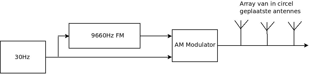 Schematic representation of a VOR beacon
DME in detail
Distance Measuring Equipment is a query and response action between the aircraft and the ground station.
The aircraft sends a sequence of pulse-pairs in the frequency range 960MHz to 1215MHz,
while the ground-station responds with the same pulses at the frequency range 962MHz to 1213MHz.
The frequency difference is 63MHz and there also is a exact delay between receive and transmission of the signals.
The aircraft sends a sequence of pulses and receives the same sequence.
The time between is causes by the fixed delay and the travel-time of the waves, offering the slant-rate.
From the slant-rate and the altitude the exact distance can be calculated, however normally just the slant-rate
is used to approximate the distance.
To assure correct operation the DME transmitter inserts random pulses called squiter.
The DME also transmits a 1350Hz morsecode identification signal (6 WPM).
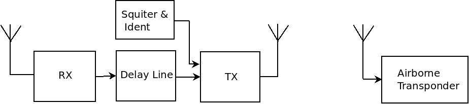 Schematic representation of a DME station
TAC in detail
A TACAN in essence is a DME interrogator where the 30Hz and 9660Hz signal is added.
Given the shorter wavelength it is possible to create a smaller phased array.
All together it is a complex signal which can be derived using analog electronics available at the time the system was invented.
The TACAN Simulator software
The absurd idea was to put all of this into a micro-controller.
A single TACAN pulse takes 3.5uSec which means that a single software iteration needs to be completed within this time.
Mind you we are talking of an iteration frequency of 286kHz !
To take the challenge i selected a PIC32MX micro-controller.
It is a 32bit micro-controller which according specs may run on 50MHz max.
An timer interrupt based approach is a no go, as the interrupt overhead causes to much performance lost.
I finally started to overclock the CPU to 60MHz by changing it's PLL settings and wrote the whole program using MIPS assembly language.
Keep in mind, this is a 5 stage pipeline processor !
It was really fun to do but one really needs to understand the quirks of the MIPS core very well !
The program in essential is a endless loop handling multiple tasks sequentualy.
To fix the timing problem, i reset a hardware timer at the begin of the loop
and and the end of the loop i consume time left (which eventually only was about 10 clock-cycles aka 2 CPU instructions !).
To achieve this tight schedule i very smartly had to enable and disable tasks depending on mode.
For instance while transmitting the morsecode id i omitted squiter as there already was enough transmitted data.
// 135Hz clock
Subbanding135HzClk:
    // To understand whats going on here,
    // Make sure you understand how 5 stage pipelining works !
    bne   t5, zero, Subbanding135HzClk_End
    addiu t5, t5, -1
    li    t5, 65
Subbanding135HzProcessBegin:

FreqGenerator135Hz_Start:
    lw    t0, Counter135Hz
    lw    t1, Azimuth
    bne   t0, t1, FreqGenerator135Hz_NoPulse
    li    t1, 31
    sw    zero, AuxBurstCounter
FreqGenerator135Hz_NoPulse:
    bne   t0, t1, FreqGenerator135Hz_End
    addiu t0, t0, 1
The TACAN Simulator hardware
I also designed a small PCB holding the simulator hardware
The PCB is also capable of simulating various other systems like:
ADF, VOR, DECCA, DCF77, GEE, LORANC and Lorenz, All totaly useless but fun to do.
I even used the same PCB for a couple of other projects.
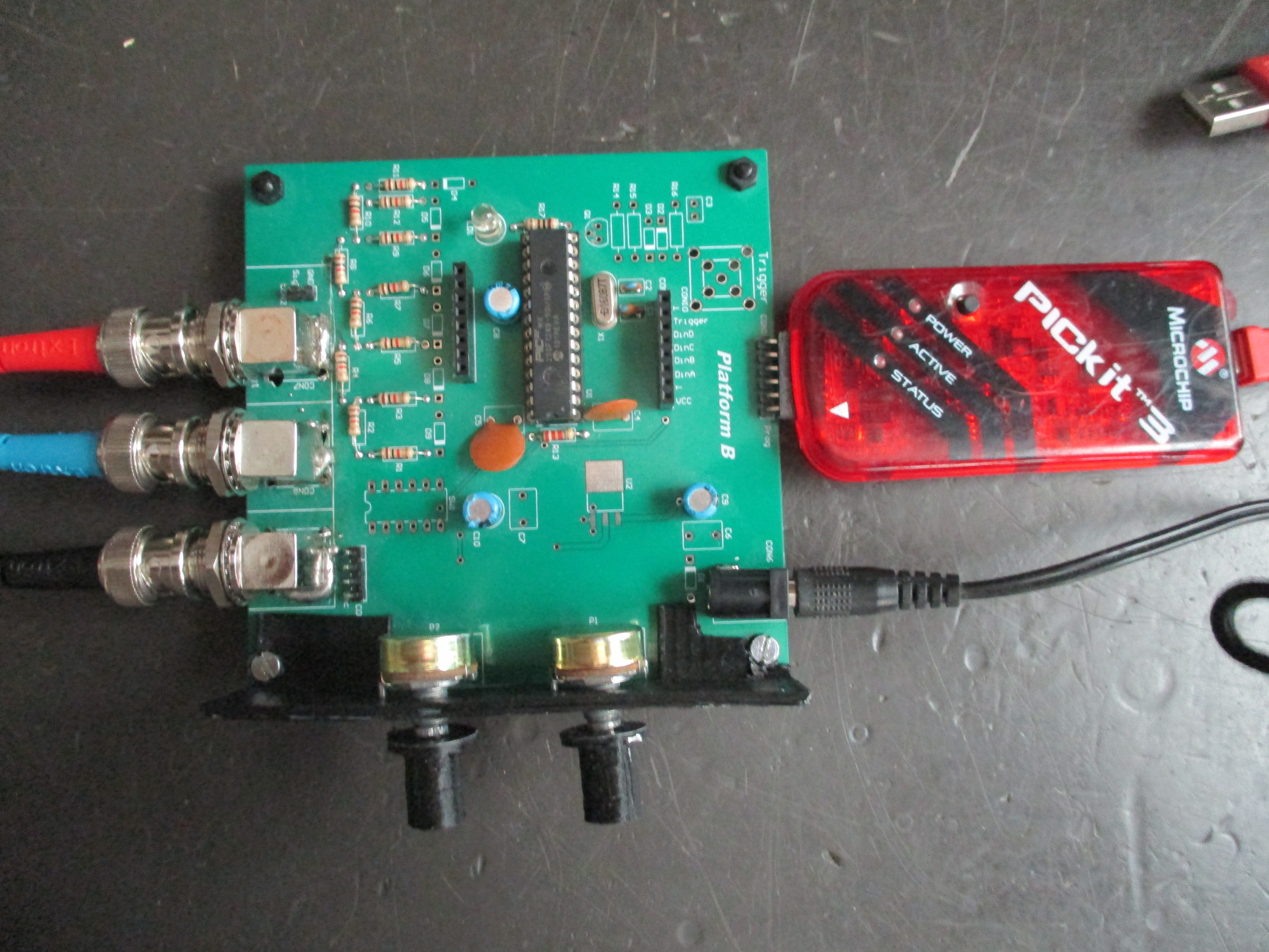 The TACAN Simulator PCB
Resulting output
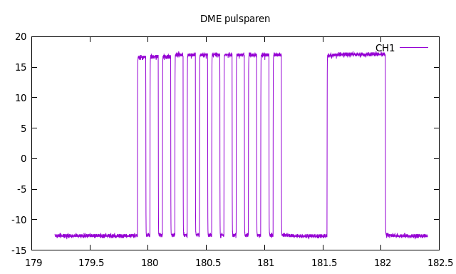 The TACAN pulse train
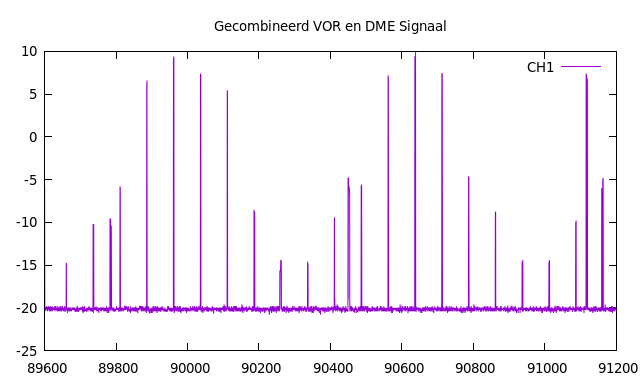 Expanded TACAN pulses with VOR modulation on top
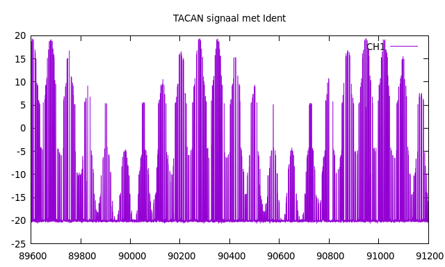 TACAN pulses with morse code ident
More information
I wrote this article originaly for a Dutch online magazine which can be found here:
DARU #18