 Schummann resonance receiver Schummann resonance receiver
Schumann resonance
Around the earth there are some electromagnetic reflective layers agitated by the radiation of the sun.
It's partial purpose is to protect man kind from this radiation.
Though it also is used for radio communication over long distances, as radio waves are also an electromagnetic phenomenon.
Surrounding the earth these electromagnetic reflective layers create a spherical cavity with a size a Little more than the earths size.
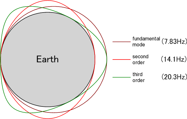 SchumannResonance around the earth
In the fifties of the past century German professor Winfried Otto Schumann predicted the existence of this cavity, and stated that it would be being agitated by electromagnetic pulses like lightning. He roughly calculated that the resonance frequency of this cavity would be around the speed of light divided by the circumference of the earth, 300000 km/sec / 40000 km = 7.5 Hz Schumann predicted the earths hart-beat on this frequency The receiver I'm about to describe is able to detect this Schumann resonance.
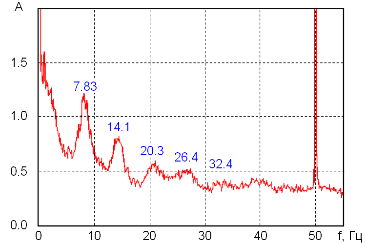 SchumannResonance frequency spectrum
Software Defined Radio
A radio receiver uses a antenna to pick electromagnetic waves from the air.
The antenna converts it to electrical signals that then are selected, amplified and demodulated using electronics.
However it is also possible to do convert these electrical signals into digital signals and do the processing using software.
This concept is called Software Defined Radio.
Generally due to the shear data to process this requires powerful computer equipment,
however with a frequency of only 7.5 Hz it is possible to do this on a light weight microprocessor.
Arduino
An Arduino is a small printed circuit board holding a Atmel 328p micro-controller powerful enough to achieve
desired purpose.
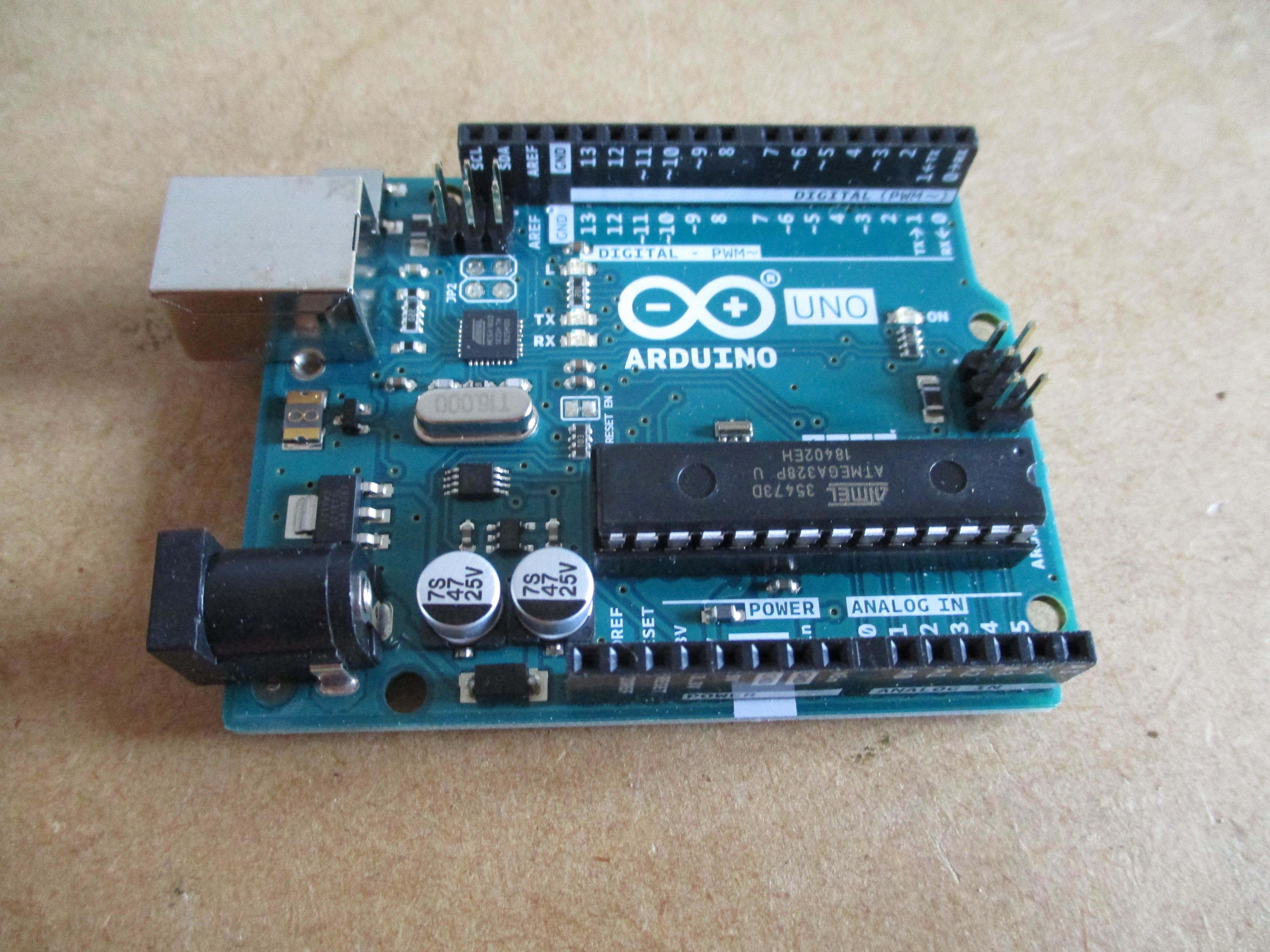 Arduino experimenters board
To this board i have added a home made circuit to condition the antenna signals so it can be picked up by the micro controllers Analog to Digital Converter. The received signals are indicated using a LED.
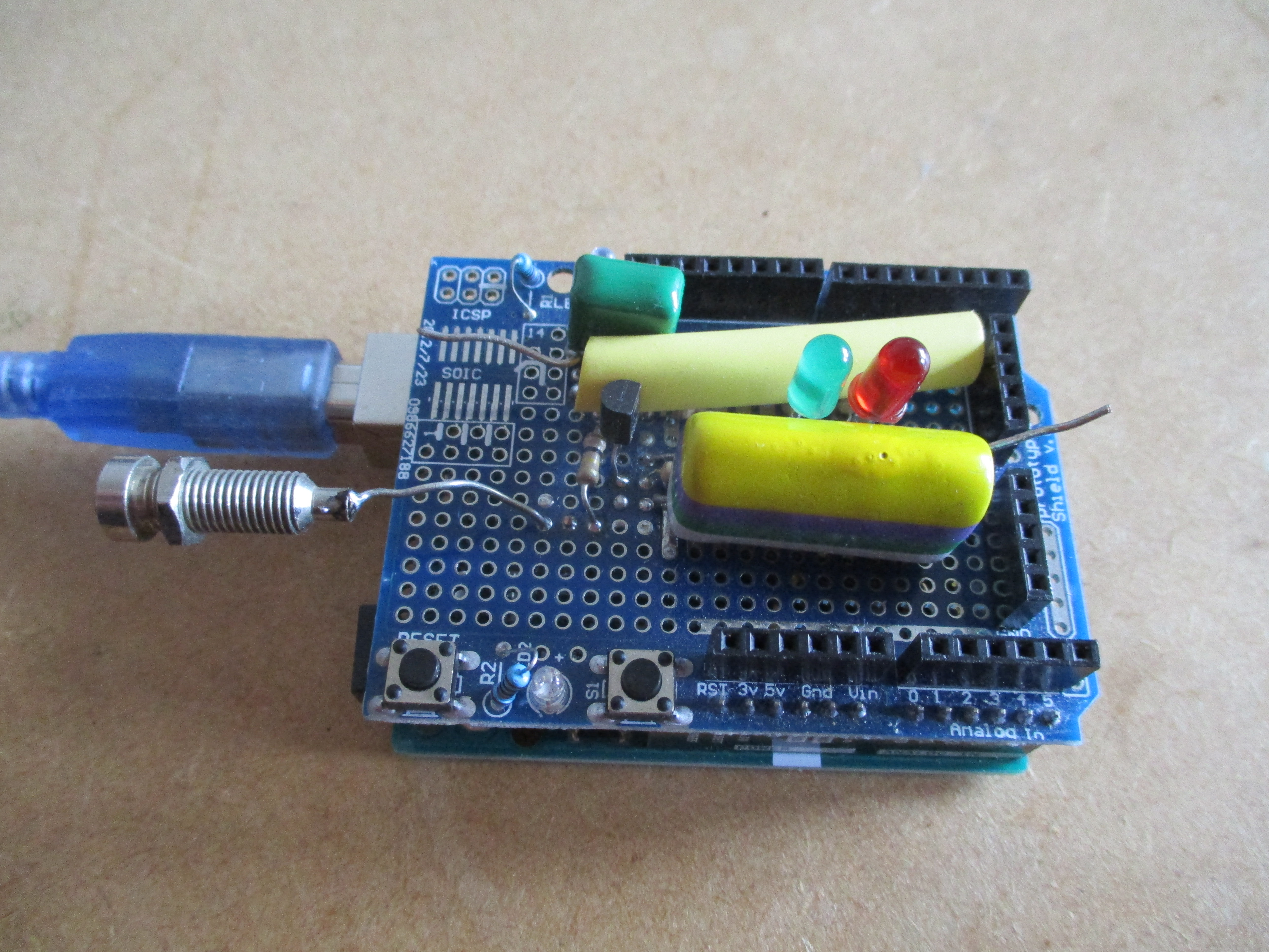 The hardware stacked onto the Arduino board
SDR Software
Although many of us think that SDR software is very complicated to create, it's not.
SDR software generally is complex, not in this case as there is no need to, nor is it the same as complicated.
Initially i have created a Finite Impulse Response Filter that basically only let's pass frequencies close around 7.5 Hz and blocks all the others.
The sample rate is determined by a accurate interrupt timer sampling at a for this purpose fairly high rate of 160 Hz.
As Schumann resonance pulses basically are short Continuous Wave pulses a peak hold circuit suffices to detect the pulses.
The detected signal is driving a LED to show the result.
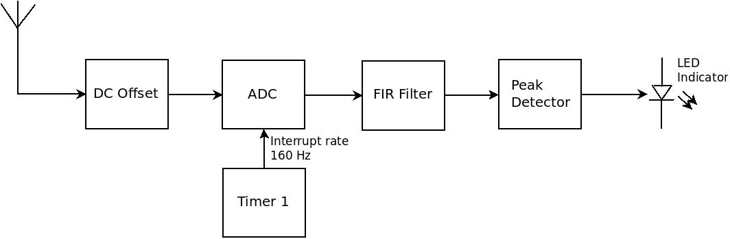 The SDR software block diagram
Code snippet:
The SDR software block diagram
Code snippet:
// Select Schumann Receiver mode
if(SchumannReceiverMode)
{
    // Init FirFilter
    FirFilter_Init(&filtertaps);

    // Start interrupt timer
    if(Enable)
    {
        TimerReload = 65535 - (2000000 / TimerInterruptFreq);
        TCNT1 = TimerReload;
        TCCR1A = 0x00;
        TCCR1B = (1 << CS11);
        TIMSK1 = (1 << TOIE1);
        sei();
    }
}
PC Program
Also i made a C# program that shows the signal on my computer and compiled it using mono.
To archive this the Arduino sampled data is send to it's serial port, which is read by the program running on my computer and plotted in blue while the peak curve is tracked in red.
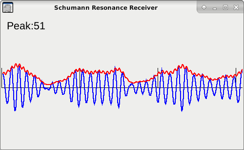 Software program running on my PC
Code snippet:
Software program running on my PC
Code snippet:
public void AddDataPoint(float dp)
{
    pts.Insert(0, new Point(0, CenterY - (int)(DelayLine(dp)*Gain)));
    if(pts.Count >= MaxX)
    {
       pts.RemoveAt(pts.Count - 1);
    }
    if(dp < 0) dp = -dp;
    peaks.Insert(0, new Point(0, CenterY - (int)(CalcAverage(dp)*Gain)));
    if(peaks.Count >= MaxX)
    {
        peaks.RemoveAt(peaks.Count - 1);
    }
    if(dp > Peak)
    {
        Peak = dp;
    }
    else
    {
       Peak -= 0.05f;
    }
    RedrawFrame();
}
I generally don't write C# code so i guess there are more efficient ways to do it. The experiment only proved to me why not to use this language for critical applications.
More information
I wrote this article originaly for a Dutch online magazine which can be found here:
DARU #25