 SAQ SDR SAQ SDR
Introduction
Recently i was attended to the annual radio transmission on 17.2kHz of the Swedish SAQ transmitter that are planned for the fourth of July 2021.
I do not in peculiar have a receiver that is capable of receiving this frequency.
Hmm ... let me see, i guess i probably can build something SDR based, lets see what we have in the junk box.
Hardware selection
Basically there is not to much to it. As signals at this frequency can be sampled using Arduino hardware.
I already crafted something using a Arduino to detect the Schumann resonance (project can be found elsewhere on this website),
Though a normal Arduino UNO will not be powerful enough to process the received signals at this frequency.
However, there are some Arduino variants that have more powerfully chips and for this project i did use
a Olimex Pinguino running a MicroChip PIC32MX440F128H.
This is a 32bit micro-controller running at 80MHz using a MIPS core that even supports some DSP instructions (although I'm not using these for this project).
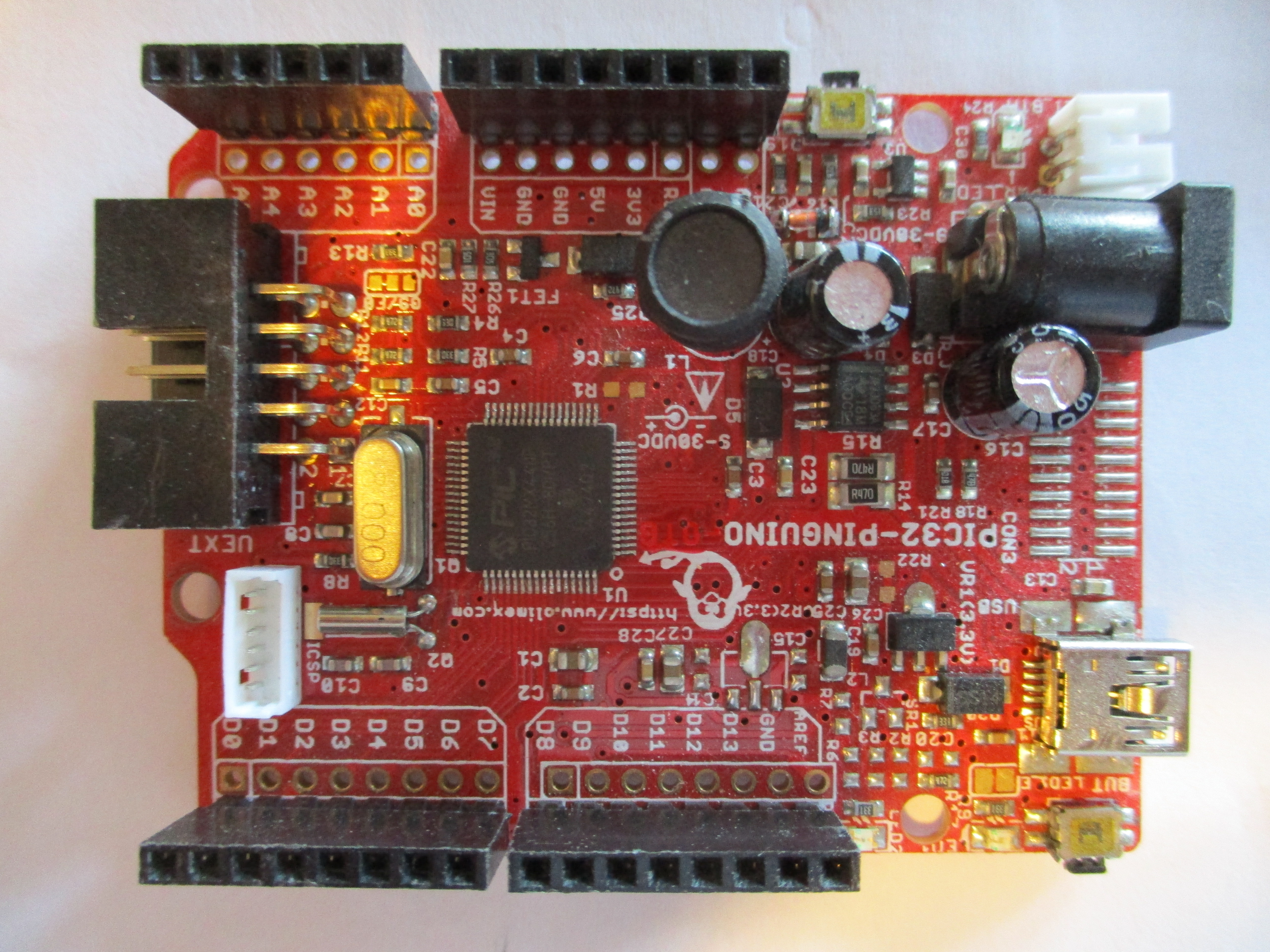 Olimex Pinguino development board
Front end
The front end of the receiver is the same i did use for the Schumann Resonance Receiver project (elsewhere on my site)
It adds some DC offset to the ADC to bring it to a class-A voltage range and a capacitor to separate the DC-offset from the antenna.
Also i had to add a PWM LPF filter to the board such it is able to produce an audible signal.
Regarding hardware concerns that's about it.
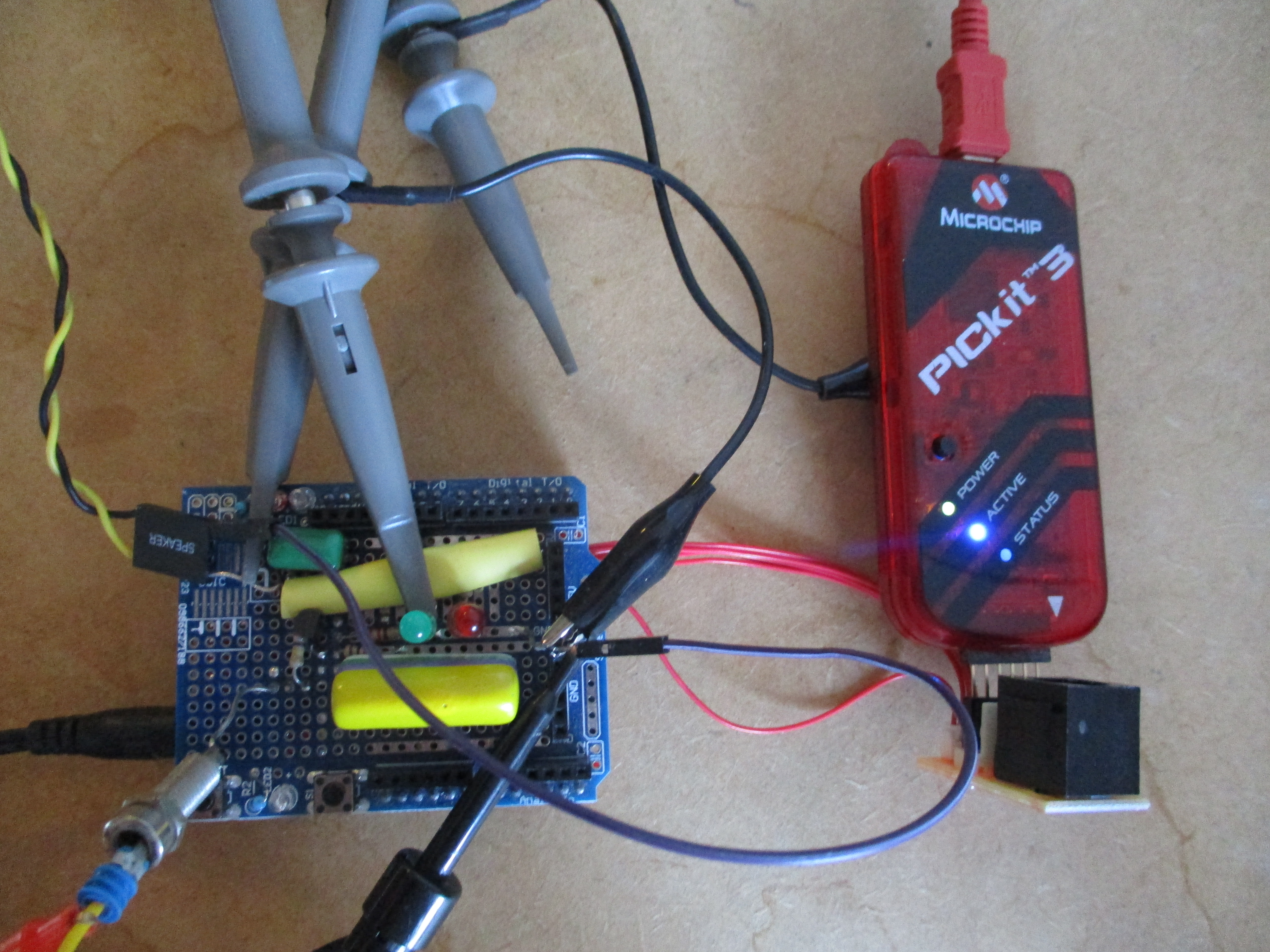 The hardware, i build on a prototyping shield.
From Analog to Digital
The PIC32MX like most modern micro-controllers does have a Analog to Digital Converter with multiple inputs.
It is possible to use one of the timers to trigger this ADC and even (if required) automatically scan over the different inputs.
This feature i have used to trigger the ADC on a sample rate of 200kHz.
The ADC automatically fills a 16 stage buffer and finishes with a interrupt to the software for further processing.
To simplify the calculations, the received signal is fed into a phase shifter resulting in the same signal 90' Shifted.
This Complex signal is multiplied with a complex local oscillator signal see further description below.
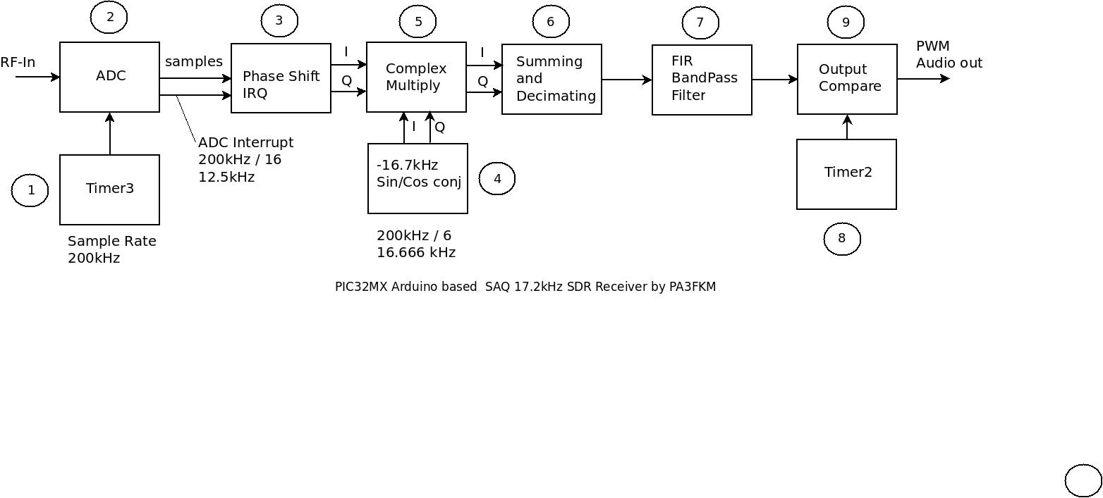 Block diagram of the SDR software.
SDR Software description step by step
(1) Timer-3 on this micro-controller is the only one that can be used to trigger the Analog to Digital Converter
It's set to a interrupt rate of 200kHz which as well will be the sample rate.
(2) Although like on most micro-controllers there are multiple Analog inputs,
There only is one ADC available, the inputs are hooked up using a demultiplexer.
I have set up the MUX for only one input while the ADC is setup for 16 inputs.
This way there is only one interrupt for each 16 samples, reducing the CPU load dramatically,
such enabling this fairly high sample-rate.
(3) The samples are copied in two buffers of which one is shifted by four samples.
This causes a phase shift of 90' resulting in a cheap Real to Complex signal conversion.
Complex calculations are fairly simple reducing CPU load.
(4) The 'local oscillator' consist of a small table only holding 6 Sine and Cosine values.
For such a small table this is the fastest solution.
Also i stored the cosine values inverted, eliminating the need for conjugating the resulting signal later.
The effective result is a complex sine-wave of -16.7 kHz (yes a negative frequency indeed).
(5) A complex multiply basically multiplies the two complex signals.
So it basically is the receivers hetrodyne mixer with 17.2kHz and -16.7kHz as input resulting in an audible frequency of about 500Hz, which is excellent for CW.
(6) In essence this is a side-band demodulator.
By adding I and Q one of the side-bands is eliminated while the other is doubled in amplitude.
We still have a sample rate of 200kHz at this point which is a bit high for the audio part of the setup.
For this reason i only use the first of the sixteen samples in the buffer.
The way the software works, this is the most easy way to decimate the sample rate.
Again this is all the reduce CPU load.
(7) The band-pass FIR filter is fairly limited, as the CPU is just not capable in handling much more.
I did use integer numbers all the way as this CPU does not have floating point capabilities and floats would therefore be to much to process.
The filter performance is a bit disappointing I'd prefer the filter direct following the ADC, but a tight FIR on 200kHz sample rate is way out of the CPU's performance.
(8) A second timer is used for the PWM output.
(9) Output Compare is a module in the micro-controller that compares the timer with a preset value.
If the timer is below this value the output pin is high, otherwise it is low.
As the timer keeps on running the output pin causes a pulse with a duty cycle proportional to value.
A simple RC low pass filter followed by an cheap audio amplifier completes the audio stage.
Building the receiver
It took me about an afternoon to build this project and another afternoon to debug and test it.
It's not really complicated, just be creative and give it a try.
Although i did use Arduino style hardware, i did not use the Arduino IDE.
This is because the complexity of the project exceeds the capabilities of the Arduino libraries
and these also are not at all very performance efficient.
So i did use the Microchip development IDE MPLabs which is freely available for Linux, Mac and Windows at the Microchip website.
For modern chips it is rather difficult to get passed all these software monstrosities.
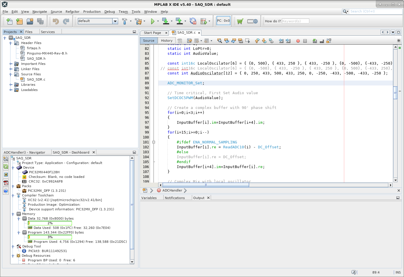 The freely available MicroChip MPLAbs IDE
Results
Well ... I'm not at all pretending i just have typed a high end receiver, far from that.
It does work for sure, i can receive the signal generator on 17.2kHz but i also have a lot of interference from the 50Hz mains that even makes it beyond the FIR filter.
Also i noticed a bothersome whistle probably the result of some reciprocal mixing of the audio sample rate and the local oscillator.
I'm not intending to solve this issue as i forgot one important issue that holds me from listening to the SAQ transmissions on the specified time.
On Sunday i have to teach the local kids how to play the guitar !
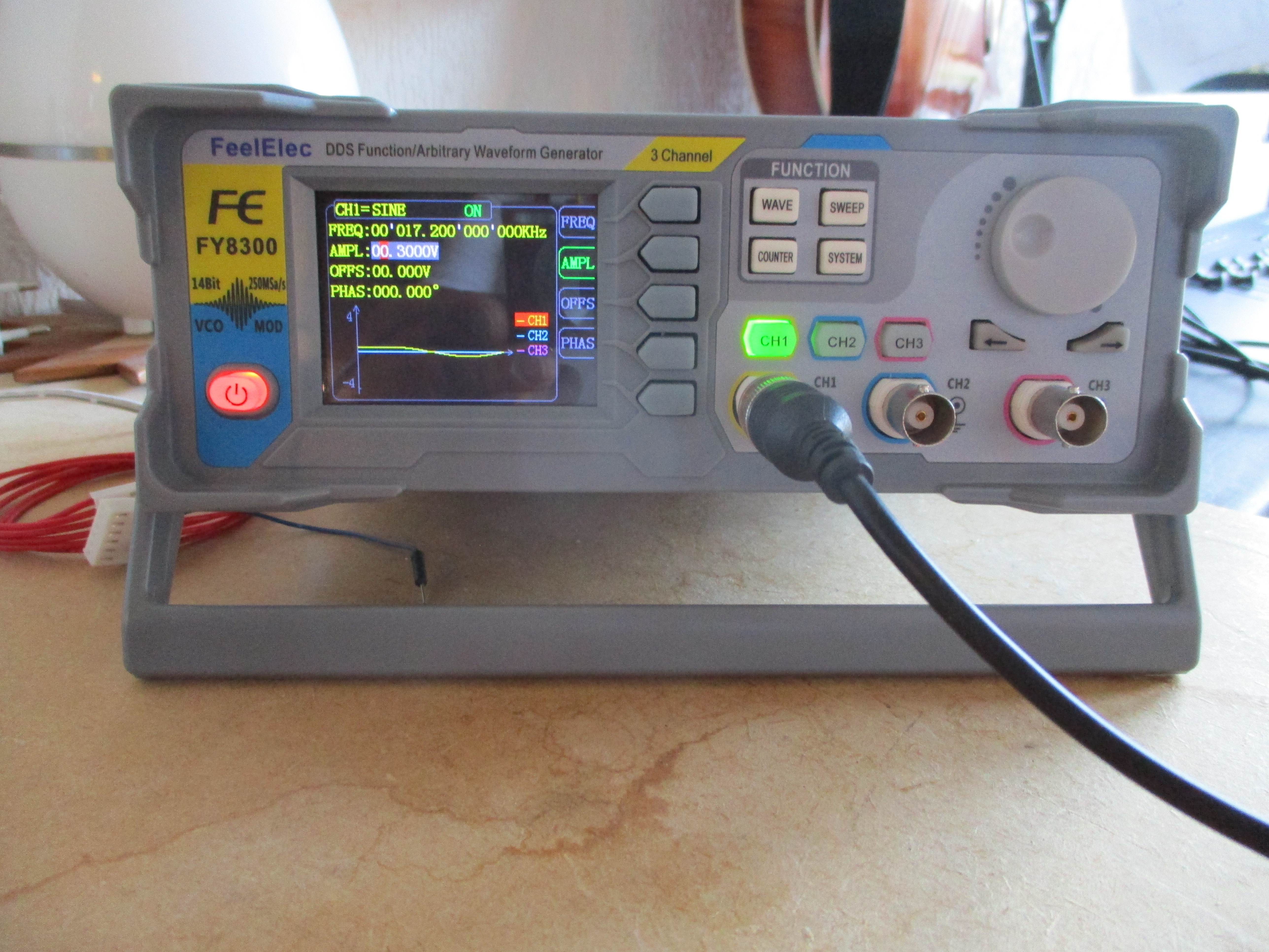 I did use a signal generator to test the setup.
Other references
The original version of this article i wrote in the Dutch language
for a free online magazine.
DARU Magazine #21