 Huff and Puff stabilizer using programmable logic Huff and Puff stabilizer using programmable logic
Introduction
As a response to my talk regarding programmable logic,
This is a practical example.
Progression comes from doing things different - Stanton Friedman
Apparently this is what late Klaas Spaargaren PA0KSB must have thought when he come up with a genius solution to attack the problem of runaway VFO's. He probably had been inspired by the concept of the 'Wadley loop' as well as 'Phase Locked Loop' and came up with what he would call 'Huff and Puff stabilizer'. A circuit in which the frequency of the VFO on its lowest digits basically is compared to a reference signal of about 40 Hz Within this range the VFO's frequency can be corrected, while the system is not able to deal with large frequency changes as happen when tuning the dial. Frequency changes as result of for instance temperature of voltage variation without the especially at the strong phase noise PLL circuits at the era would cause. With a few Hertz change. the VFO slowly would wiggle around the tuned frequency unnoticed.
Practical implementation
Following an earlier explanation regarding programmable logic elsewhere on my site it seemed to me nice to come up with a example using a CPLD.
An FPGA would work as well and i will explain later why in this case a CPLD would be the smarter choice.
The setup consist of the following parts:
(1) The VFO, a Hartley i found in my junk box. No idea why i once build it.
It's range is approximately from 12MHz up-to 15MHz and certainly not very stable in frequency such being an excellent candidate for the experiment.
I had to add some extra gibberish to the VFO in order to control the frequency by the CPLD and feed the output into the same CPLD.
Here such goes like, that's a nice blue capacitor, it might nice fit on the board, value i don't care, ohh here's 100kOhms laying on the table, that one is nice as well. Using a varicap ? why would i any diode has capacity.
(2) A CPLD experimenters board, already presented in my article regarding programmable logic.
There is an onboard 50MHz xtal oscillator which is used as the base for the reference frequency.
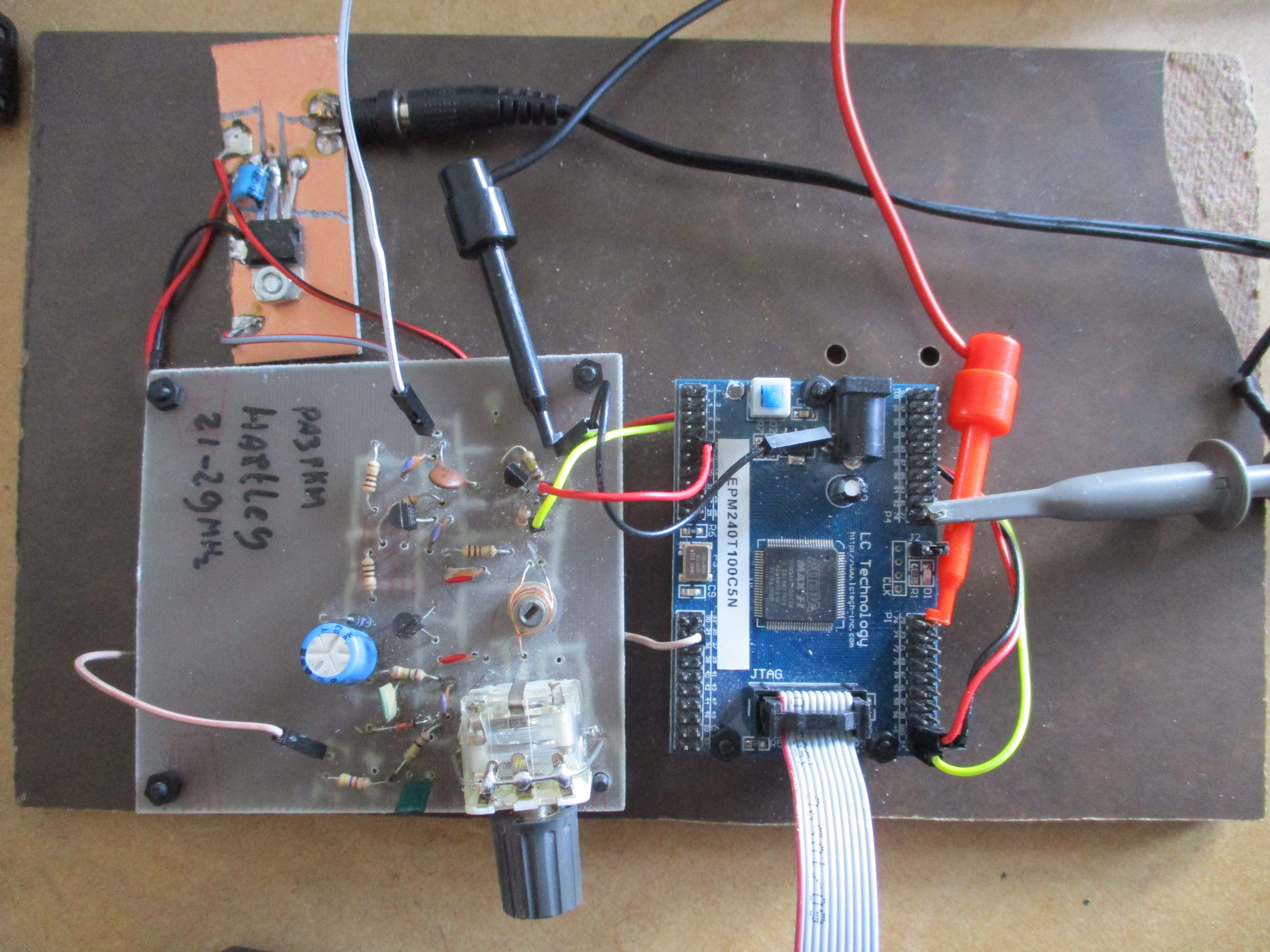 The complete test set-up
HDL
The rest of the project is defined in the 'Hardware Description Language' which i have subdivided into
three processes:
(1) RefClockGenerator, just a frequency divider. 50MHz xtal ref as a input,
about 45 Hz on the output represented by the signal 'RefClk'.
(2) VFORefGenerator, exactly the same as the previous process but with the VFO frequency as the input signal.
The result is the signal 'VFOref'.
(3) HuffAndPuff, the process that compares the two created ref signals and corrects the VFO accordingly.
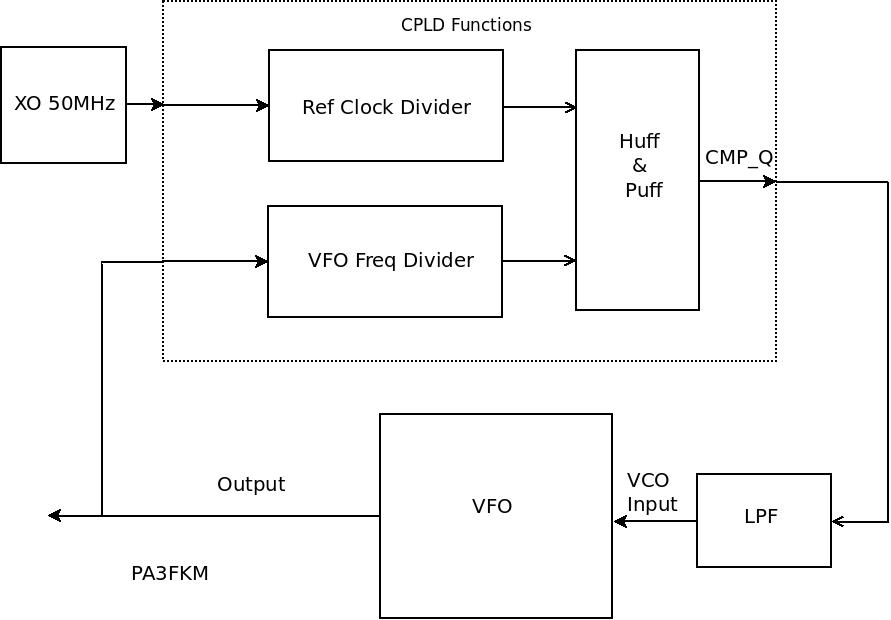 Schematic setup
Before trying the Huff and Puff concept, i first tried a basic phase locked loop by just comparing RefClk and VFORef using a XOR function. If you select components by their shape or what is laying on the table rather than making calculation the result is unlikely to be optimal. A giant phase-noise came from the oscillator, never-less it was nicely stable on 12.5MHz and a nice correction signal could be seen on the oscilloscope
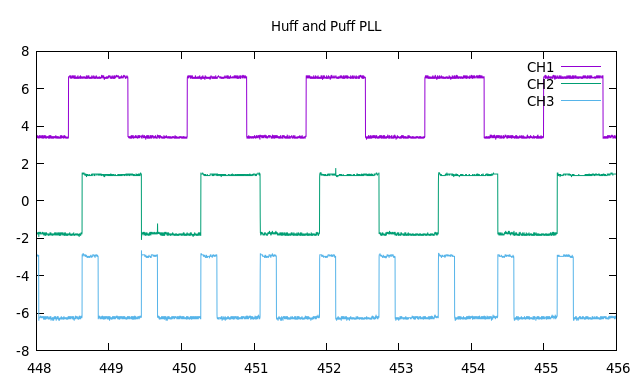 Divided VFO frequency (CH1), Reference frequency (CH2) and the PLL correction signal (CH3)
Being satisfied with the result, it now was time to try the Huff and Puff concept. This again was a challenge on it's own as the integrator for controlling the VCO was far from optimal for the small corrections intended (it worked nice for 12kHz steps). Despite after some twiddling after re-tuning the VFO it was nicely kept within the 45Hz raster.
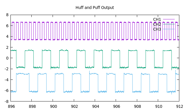 The divided VFO frequency (CH1), 45Hz ref (CH2) and the Huff And Puff correction signal (CH3)
VHDL Code
I'm not going into detail here but I'll show some code snippets instead.
Here the input and output signals are defined.
Roughly said a std_logic is a signal that can be 1 or 0.
Entity HuffAndPuff is
   Port
   (
       VFO_in         : In  std_logic;
       VFO_RefOut     : Out std_logic;
       --
       HuffPuff_Q     : Out std_logic;
       LED            : Out std_logic;
       --
       ClkRefOut      : Out std_logic;
       Clk50MHz       : In  std_logic
   );
End HuffAndPuff;
Some variables (signals) that are needed. A std_logic_vector is more or less a register.
Code snippet:Signal RefClkDiv : std_logic_vector(23 DownTo 0); Signal VFOClkDiv : std_logic_vector(23 DownTo 0);
Since multiple things happen at the same time (unlike a CPU where everything happens sequentially), The functions are subdivided into multiple processes triggered by some form of clock signal. This one just increases the register by one each tick. On overflow it rolls back to 0 again.
Code snippet:
RefClockGenerator : Process(Clk50MHz)
Begin
   If Clk50MHz'Event And Clk50MHz='1' Then
      RefClkDiv <= RefClkDiv + '1';
   End If;
End Process RefClockGenerator;
For the smart asses among us, indeed you can use also: if rising_edge(Clk50MHz) thenFor the PLL experiment all i had to to was
Code snippet:HuffPuff_Q <= VFORef XOR RefClk;
Not really the best way to create a phase correct signal but basically this is it. The Huff and Puff part wasn't to difficult either
Code snippet:
HuffAndPuff : Process(VFORef)
Begin
   If VFORef'Event And VFORef='1' Then
      HuffPuff_Q <= Not RefClk;
   End If;
End Process HuffAndPuff;
This is basically a D-Flip-Flop like a 7474. The Q-output at times is compared to the RefClk such locking the VFO to any multiple of this reference frequency. Sure there are better ways to do it, I'll pass it on to the 'we know what we do' department. Multiple HAMs have experimented using this concept and a quick search on the internet offers complete building plans. The same way i once implemented a PLL into a CB radio as well as some other weird experiments to keep the brain stimulated.
Using a FPGA in stead of a CPLD ?
The code will run on a FPGA without changes, only pin-numbers and device type need to be reconfigured.
However a FPGA is far more complicated than a CPLD having the need of multiple voltages and a configuration device.
Also due to its complexity signal progression times are less predictable.
In this simple and low frequency design this is not at all a problem but it sure can be on higher performant designs !
Small phase shifts between 350MHz signals are inevitable and to get rid of those a very well understanding of profiling is needed.
Resume
The images are a bit poor
I'm not a good photographer, did not manage to have nice pictures from a analog osciloscope.
So i grabbed data using a digital scope and presented them using gnuplot.
Also my experiment set-up will cause grey hear for some people.
You have to excuse me, I'm not that technical.
A Dutch version of this article can be found in the DARU magazine no 19.