 DataModem DataModem
Introduction
For a project as a proof of concept i wanted to use a standard Arduino UNO
as a multi mode data modem, uing a minimal of extra hardware.
Initialy the goal was to be able to receive and decode RTTY signals,
however soon i needed a test signal so i implemented transmitting,
soon followed by change in tones an reverse, well you probarly know how this went.
Software implementation
Though i like to fiddle with Arduino hardware, i'm not to enthousiastic about the Arduino IDE,
nor it's hightly flexible and portable but limmited libraries.
So although i recently started to go without the famous blue programmer and use the standard bootloader,
i still go for standard .C and .H files, create my own Hardware Abstraction Layer (drivers)
And use a Makefile that does al the work regarding compiling flashing and such.
Hardware selection
To simplify things i tried to do as much in software as i could manage such keeping
required hardware to a minimum and available of the shelf.
So i selected a standard Arduino Uno board as a platform to base the whole device on.
This board embeds a Atmel328p Microcontroller which i use as a kinda Digital Signal Processor.
A home brew Arduino shield offers some form of signal conditioning though it would do without as well.
Receiving
For receiving the audio signal goes almost straight into one of the I/O pins.
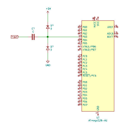 Interfacing the Audio signal to the MicroController
This peticular pin causes an interrupt on both leading and trailing edge of the audio signal. Using one of the MicroContoller timers, the period time is measured such determining the frequency.
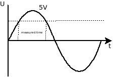 Period Time Measurement
After decoding the MARK and SPACE tones they are fed into a real time software based shift 5 bit UART implementation from which the Bauddot can be retrieved and converted into ASCII send out to the Arduino's serial port.
Transmitting
Transmitting Baudot code is basicly the other way around.
Text is received via the Arduino's serial port, converted into Baudot
and the audio tones are generated using a Timer toggling one of the I/O pins.
This is followed by a fairly simple Low Pass Filter.
 DataModem PCB
PCB
To make things easieer a Arduino Shield was created.
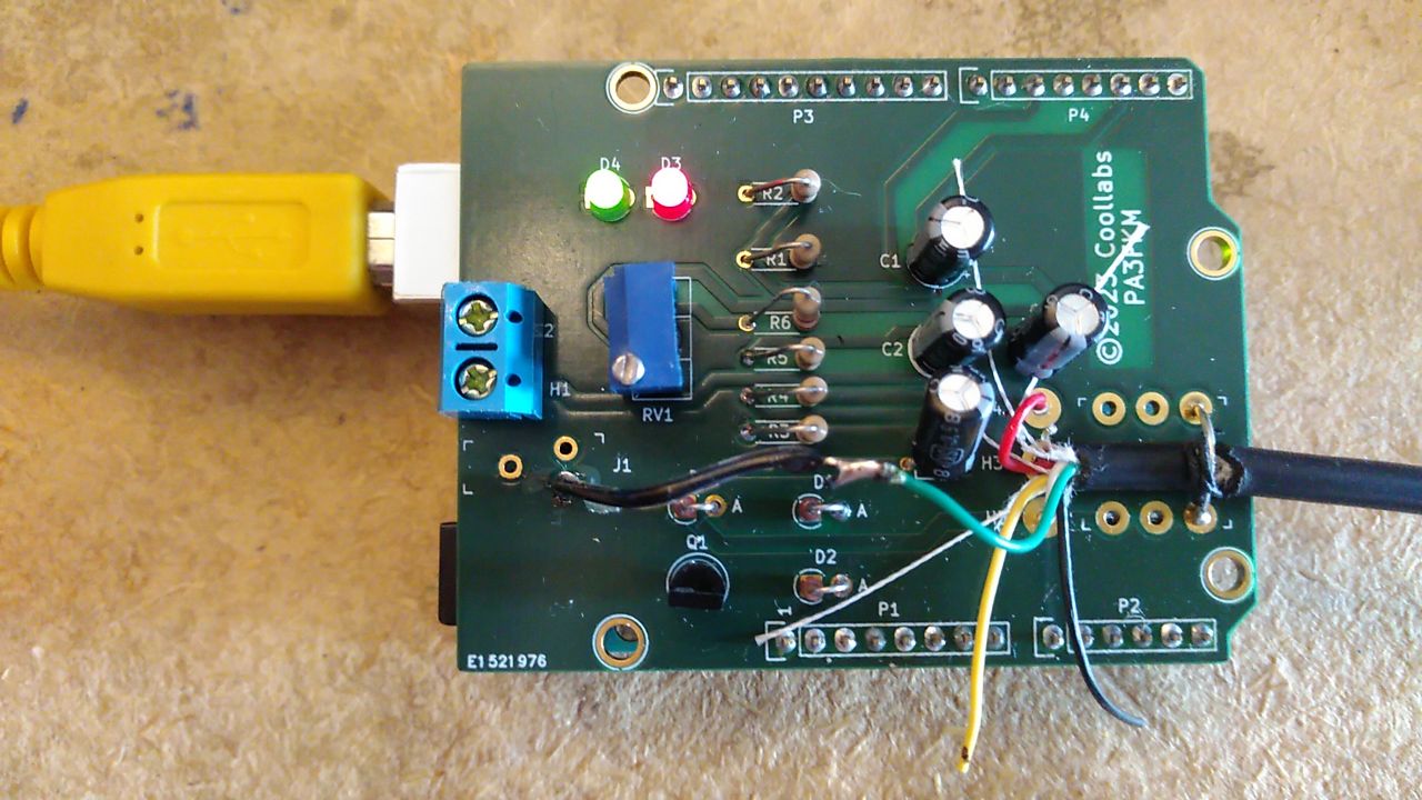 Arduino DataModem Shield
This PCB features as described a digital audio input, as well as a analog input to support modern digital modes, a audio output followed by a LPF and a transistor to switch the radio between transmit and receive.
Results
The decoded was mainly tested using the German Wheater forcast station DDK2 on 10.100 MHz
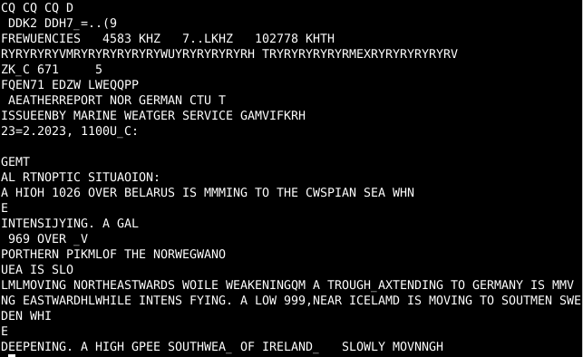 DDK2 Weather forecast
Also sucsesfull transmissions between two Baofeng handy talkers was archieved.
Other references
A Dutch artikel regarding the incitement to this project can be found in a free online magazine on page 26.
DARU #35