 Arduino PLL Arduino PLL
Introduction
I came to the idea to use a cheap MicroController to create a PLL chip.
The fastest to do this probarly is by using Arduino hardware for the MicroController,
combined with a fairly simple and straigth forward Voltage Controlled Oscilator or VCO.
The oscilator
The oscilator is a Seiler oscilator, which basicly is of a modified Collpits type.
It's followed by a simple buffer to drive the Arduino input.
The frequency is controlled by a diode varicap diode preceded by a LPF.
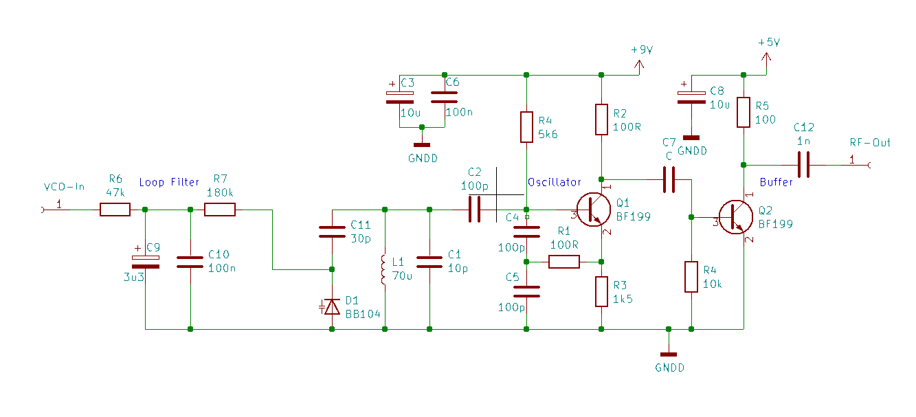 The schematic for Oscilator
Mind that this buffer makes a square wave and such has lots of harmonics ! To actualy use the signal for a radio, beter use another buffer thats more linear to sinewave.
The MicroController
As said, for the MicroController I just used a Arduino Uno containing a Atmel 328P processor.
The whole setup now looks like this.
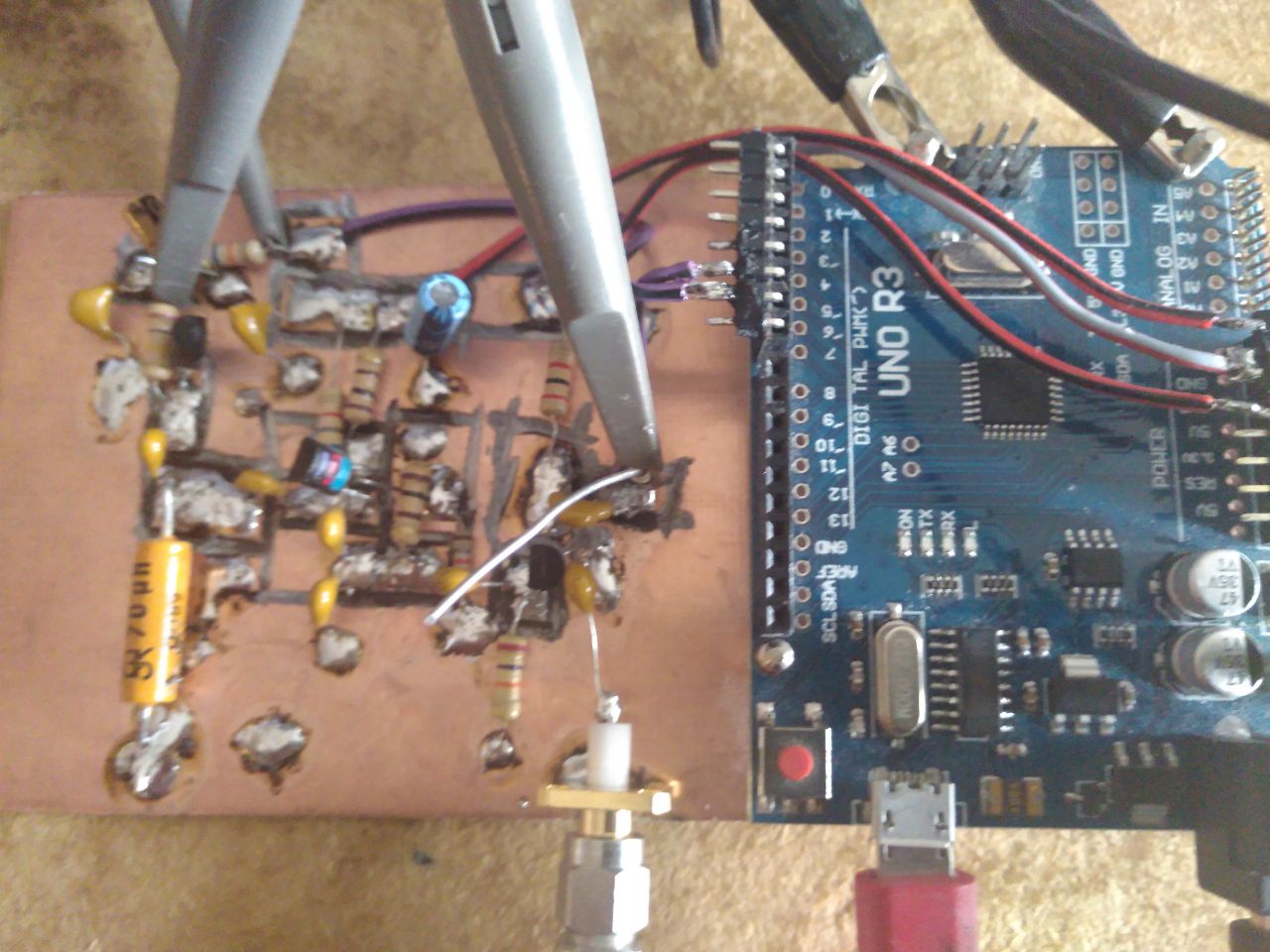 Arduino PLL test setup
The Firmware and results
I used a free running timer as a reference for the frequency.
The RF-Signal from the buffer is fed to a InteruptRequestLine of the Atmel chip.
Each time on raising edge a interupt is executed in which the timer is compared to a desired value,
after which the timer is reset, counting for the next interrupt.
Depending on the result initialy i moved a pin High or Low to driver the LPF for the VCO.
This was however to much for stable results.
Than i used another timer to PWM the output pin based on the magnitude of fault signal.
This dramaticly improved the stability of the frequency.
Oddly enough the whole interrupt routine consists of just two lines.
It's not the amount of program lines but their efficiency that make a project sucsesfull !
Note that i actualy made a frequency locked and not a phased locked loop,
Never the less it worked pretty nice.
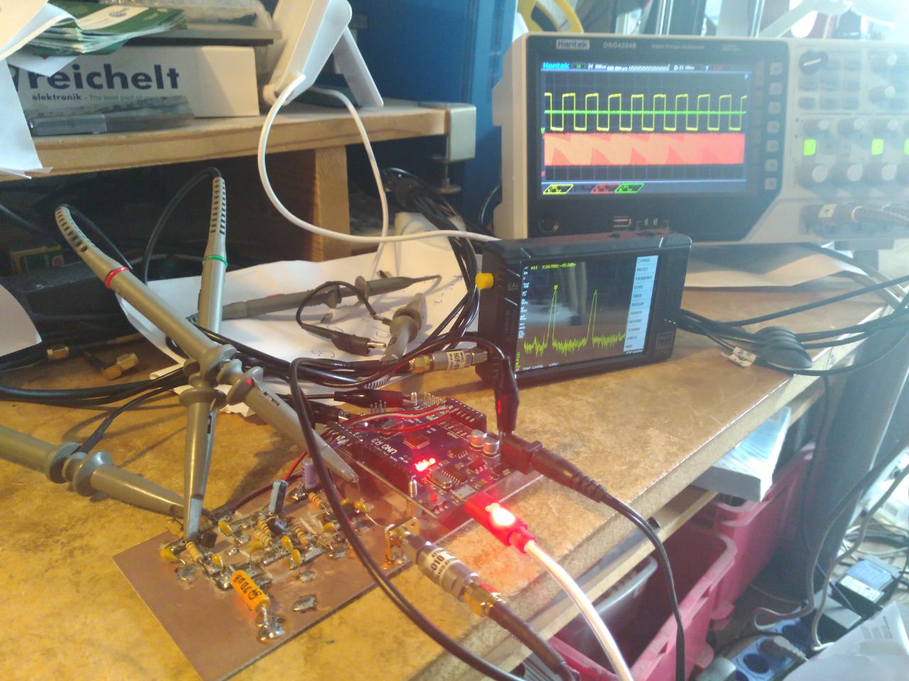 What the project looked like
Further reference
A Dutch language article i wrote about this experiment can be found at
Page 2 of Razzies Sept 2024